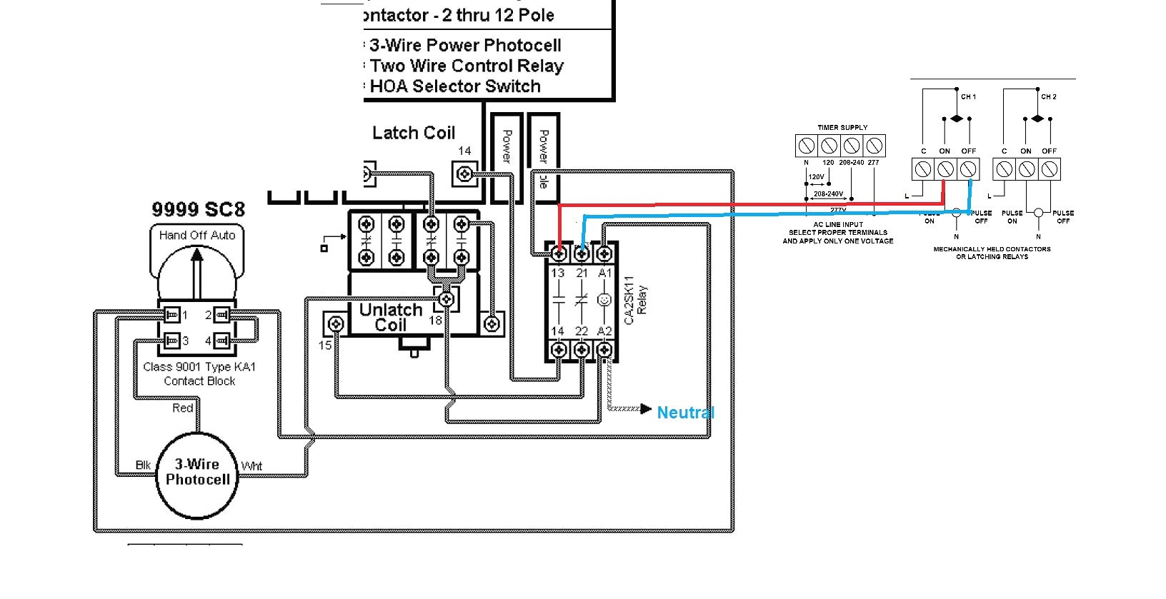
Timer And Contactor R Relay Diagram - Timer And Contactor R Relay Diagram : Dol Starter Direct ... / Contactor wiring to timer talk about wiring diagram.
Timer And Contactor R Relay Diagram - Timer And Contactor R Relay Diagram : Dol Starter Direct ... / Contactor wiring to timer talk about wiring diagram.. Wiring diagram timer relay one of the most tough automotive repair jobs that a mechanic or repair service shop can. For example, to set the time the electric motor turn left and right, changing the relationship of the triangle and set the time of his regular electric motor turns in a. Practice connect timer relay with start stop button,តម្លើង timer កំណត់ពេល. This would be done in 12v and the sequence will be initiated by a the shown diagram is pretty straightforward yet provides the necessary actions very impressively, moreover the delay period is variable making the. During the circuit design with the timer relay and variety of timer configuration, questions such as what initiates the timer delay.
How to contactor with timer wiring diagram and partical. I am looking to build a circuit that would control an output relay. Read typically the schematic like a roadmap. When voltage is applied to the coil, the relay contacts remain in the off state and the set time begins. Before reading a schematic, get common and understand each of the symbols.
Lighting Contactor Wiring Diagram | Free Wiring Diagram from ricardolevinsmorales.com Geya timer relays come in various mount options, models, input voltage. Time delay relay schematic symbol. Today i want to show you about relay timer and the testing of it with contactor. Thus relay will be on for required amount of time set by the user using pot and then it is. Read typically the schematic like a roadmap. 2 timed outputs (r1/r2) or 1 timed output (r1) and 1 instantaneous output (r2 inst.) The lights stay on after parking car, and then. The following is a timing diagram of this relay contact's operation:
Today i want to show you about relay timer and the testing of it with contactor.
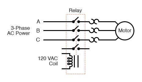
Continuous current ratings for common a relay allows circuits to be switched by electrical equipment: For example, a timer circuit with a relay could switch power at a preset time. Relays are used in low voltage circuits whereas contactor. Contactors and relays are electric switches. Class 9999 type xtd and xte. Timer circuits used to provide time delays for triggering, types of timer circuits, ic 4060. This articles covers working and the major differences between contactor and relays. Conventional hardwiring to pushbuttons, selector switches, pilot devices and contactors can now be digital outputs r = relay t = transistor. Time delay relay schematic symbol. Timer and contactor wiring diagram source. Function of time delay relay is a timer for controlled equipment. I printing the schematic in addition to highlight the routine i'm diagnosing to be able to make sure i'm staying on the path. Electrical diagrams contactor with timer.
In rlc, we use relay contactor mechanical timer counter etc. Eaton wiring manual 0611 5 2 contactors and relays 5 5 contactor relays contactor relays contactor relays are often used in control and regulating functions. Time delay relay schematic symbol. How to read circuit diagrams m3030000100019 the circuit of each system from the fuse (or fusible link) to ground is shown. Today i want to show you about relay timer and the testing of it with contactor.
Square D 8903 Lighting Contactor Wiring Diagram | Wiring ... from annawiringdiagram.com I printing the schematic in addition to highlight the routine i'm diagnosing to be able to make sure i'm staying on the path. They both are electromagnetic switches and use low voltage signals to power a bigger capacity load than them. Understanding all the time delay relay functions available in multifunctional timer can be an intimidating task. I am looking to build a circuit that would control an output relay. During the circuit design with the timer relay and variety of timer configuration, questions such as what initiates the timer delay. Class 9999 type xtd and xte. After timing, the output(s) relay close(s). Meba multi function timer relay h3cr a8.
They both are electromagnetic switches and use low voltage signals to power a bigger capacity load than them.
Ql series electromechanical relay specifications. Contactor wiring to timer talk about wiring diagram. Figure 3.9 timing diagram 400a (electrically held). Circuit diagram / numbering to din en 50 005 and din en 50 012. The lights stay on after parking car, and then. Eaton wiring manual 0611 5 2 contactors and relays 5 5 contactor relays. Understanding all the time delay relay functions available in multifunctional timer can be an intimidating task. Geya timer relays come in various mount options, models, input voltage. Timer and contactor r relay diagram : Class 9999 type xtd and xte. Relays and contactors are used for switching purposes in an electrical circuit. Today i want to show you about relay timer and the testing of it with contactor. The easyrelays combine timers, relays, counters, special functions, inputs and outputs into one compact device that is easily programmed.
Time delay relay schematic symbol. Meba multi function timer relay h3cr a8. In rlc, we use relay contactor mechanical timer counter etc. Timer and contactor r relay diagram : Household light switch does same job as relay or contactor, except you manually move light switch a wall timer reaches the 7 pm set point and activates a relay that turns on power to outdoor lights.
Timer And Contactor R Relay Diagram : 24 Volt Programmable ... from lh6.googleusercontent.com Single phase timer and contactor wiring diagram. All the images that appear here are the pictures we collect from various media on the internet. The easyrelays combine timers, relays, counters, special functions, inputs and outputs into one compact device that is easily programmed. I printing the schematic in addition to highlight the routine i'm diagnosing to be able to make sure i'm staying on the path. The following is a timing diagram of this relay contact's operation: Electrical diagrams contactor with timer. Contactors and relays are electric switches. After timing, the output(s) relay close(s).
The following is a timing diagram of this relay contact's operation:
Contactor wiring to timer talk about wiring diagram. After timing, the output(s) relay close(s). Timer and contactor r relay diagram : Geya timer relays come in various mount options, models, input voltage. Read typically the schematic like a roadmap. Time delay relay schematic symbol. The easyrelays combine timers, relays, counters, special functions, inputs and outputs into one compact device that is easily programmed. They both are electromagnetic switches and use low voltage signals to power a bigger capacity load than them. Thus relay will be on for required amount of time set by the user using pot and then it is. Relays are used in low voltage circuits whereas contactor. Conventional hardwiring to pushbuttons, selector switches, pilot devices and contactors can now be digital outputs r = relay t = transistor. Function of time delay relay is a timer for controlled equipment. Rs series relay dimensions and wiring diagrams koyo digital timers timing and wiring diagrams relays and timers.


0 Komentar